7 Tips for 480V to 13.8kV Step Up Transformer Specs?
Selecting a transformer for a 480V industrial system feeding a 13.8kV network demands more than matching two voltage numbers. The correct 480v To 13.8kv Step-Up Power Transformer Specs must reflect load behavior, installation conditions, protection, and future expansion. A small mismatch can create overheating, nuisance trips, poor voltage regulation, or expensive downtime. The nameplate is only the beginning.
This guide presents seven practical tips for evaluating step-up transformer specifications. It examines kVA capacity, phase arrangement, frequency, impedance, insulation levels, cooling class, and connection design. It also considers tap settings, grounding, short-circuit strength, enclosure requirements, and site elevation. For example, a 2,000 kVA transformer in a clean indoor room may require different cooling and enclosure decisions than one installed outdoors near salt air. Details matter.
Field experience shows that calculations often look precise before real operating data arrives. Motor starting current, harmonics from variable-frequency drives, and seasonal loading can change the design margin. Do not assume the first load estimate is perfect. Recheck it. A qualified engineer should verify coordination studies, utility requirements, testing documents, and applicable electrical standards before purchase. This article is educational, not a substitute for a project-specific engineering review. Even experienced teams can miss a practical issue, such as cable termination space or restricted maintenance access. The best specification is clear, testable, and connected to actual operating conditions. That is where reliability begins.
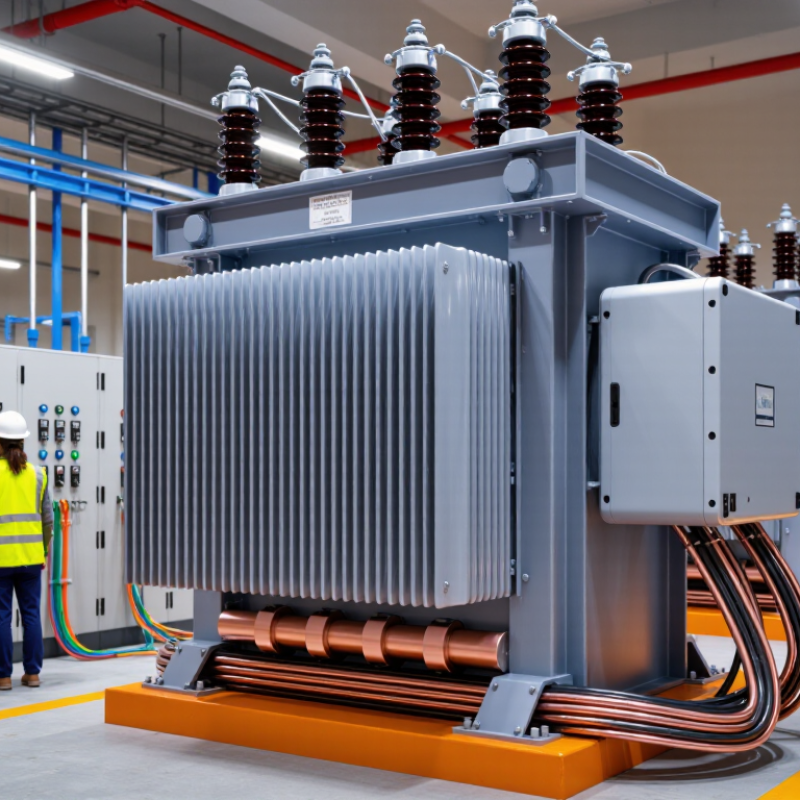
Define Voltage, Power, and Frequency Requirements
A 480V to 13.8kV step-up transformer needs a precise voltage definition. State 480V and 13.8kV as line-to-line values, then confirm the system phase and grounding method. The basic ratio is 28.75:1, but the final design also depends on tap range and voltage regulation. Specify 50 or 60Hz clearly. Frequency changes affect core flux, heating, and insulation stress. IEEE C57.12.00 and IEC 60076 provide widely used transformer requirements for ratings, insulation, and testing.
Tip 1: Size power from measured demand, not connected load alone. Record motor starting current, harmonic-producing equipment, future expansion, and emergency loading. Express capacity in kVA or MVA. A practical design may include spare capacity, but excessive oversizing can increase no-load losses. The U.S. Department of Energy’s distribution-transformer analysis reports that transformer losses represent roughly 2.5% of national electricity use, showing why efficiency deserves attention.
Tip 2: Define the duty cycle and ambient conditions. A transformer feeding a 13.8kV industrial bus may face repeated motor starts, uneven phases, or dusty outdoor conditions. Specify continuous kVA, short-time overload, cooling class, and temperature rise. I would not assume 60Hz is universal. Some facilities still use 50Hz equipment, and a small frequency error can become an expensive design mistake. Review the load study twice.
Select Transformer Capacity and Suitable Winding Configuration
For a 480V to 13.8kV step-up transformer, capacity selection begins with the real load profile. Calculate connected load, demand load, motor starting current, and expected expansion. A 750 kVA unit may suit a steady 600 kVA demand, but large motors can change the decision. Check the short-time overload requirement. It matters.
Tip: Leave practical spare capacity, not excessive capacity.
Winding configuration affects safety, grounding, and system behavior. A common arrangement uses a low-voltage delta winding and a high-voltage grounded-wye winding. This can provide a neutral point for protection and improve ground-fault detection. However, the correct choice depends on the upstream and downstream systems. Review phase relationships, zero-sequence current, and harmonic-producing loads before approval. In some projects, engineers select a familiar configuration too quickly. That deserves a second look.
Tip: Confirm grounding compatibility with the complete power system.
Specify impedance carefully. Higher impedance can reduce fault current, but it may increase voltage drop during motor starting. Record the required tap range, insulation level, cooling method, altitude, ambient temperature, and enclosure type. Outdoor installations may need stronger weather protection. Include routine testing and factory documentation in the purchase specification. A clean nameplate helps later maintenance. It does not replace a proper study. Short-circuit calculations and coordination reviews should confirm the final kVA and winding design before construction.
Specify Insulation, Cooling, and Voltage Regulation Features
A 480V to 13.8kV step-up transformer needs more than a voltage ratio. Insulation, cooling, and regulation determine its field performance. Specify the primary and secondary voltage clearly, including frequency, system grounding, and connection arrangement. Confirm the required basic insulation level and power-frequency withstand voltage. These values should match the installation altitude, lightning exposure, and switching conditions.
Use sealed or liquid-filled construction only after reviewing maintenance needs. Specify the insulation liquid, temperature-rise limit, and enclosure rating. Natural oil cooling may suit moderate loads, while forced-air cooling can support higher demand. Include ambient temperature, overload duration, and expected load cycles. A small detail matters here: blocked radiator airflow can reduce usable capacity. I have seen capacity estimates fail because actual site conditions were ignored.
Voltage regulation deserves equal attention. State the acceptable secondary voltage range at full load, not only the no-load ratio. Specify impedance, tap range, and tap locations. An off-circuit tap changer may work for stable systems, but frequent voltage changes require a different solution. Check fault current before finalizing impedance. Lower impedance improves regulation, yet it can increase short-circuit stress. Technical teams should verify insulation coordination, cooling calculations, and tap settings against applicable electrical standards. The specification may still need revision after a load study. That is normal.
Evaluate Protection, Safety, and System Compatibility
A 480V-to-13.8kV step-up transformer is not just a voltage converter. Its specifications must fit the entire electrical system. Confirm rated power, frequency, impedance, insulation level, and available fault current. A qualified engineer should compare these values with generator output and utility requirements. Small mismatches can cause nuisance trips, excessive heating, or unstable voltage. The nameplate is only a starting point. Good design requires field verification.
Protection deserves direct attention. Specify primary and secondary overcurrent protection, surge arresters, ground-fault detection, and coordinated relays. Check interrupting ratings against the calculated short-circuit current. Include temperature sensors and alarm contacts where continuous operation matters. The 13.8kV side needs proper clearances, barriers, grounding, and lockable access. Never treat an enclosure as a substitute for a verified grounding grid. That assumption fails in the field.
System compatibility also includes phase arrangement, tap range, vector group, neutral treatment, and inrush behavior. Confirm that downstream switchgear accepts the transformer’s fault-duty and insulation ratings. Review cable terminations, maintenance access, arc-flash labeling, and emergency isolation points. Factory test reports, inspection records, and an independent design review improve reliability. I would also challenge the initial load forecast. Many projects underestimate motor starting current. A conservative specification may cost more, but an unclear one costs safety and uptime.
7 Tips for 480 V to 13.8 kV Step-Up Transformer Specs
Evaluate protection, safety, and system compatibility using calculated full-load currents for a three-phase transformer.
The chart uses the standard three-phase relationship I = kVA × 1,000 ÷ (√3 × V). At the same transformer rating, the 480 V winding carries substantially higher current than the 13.8 kV winding, which directly affects conductor sizing, overcurrent protection, bus ratings, and switchgear selection.
Confirm the seven key items before final specification: voltage ratio, frequency, kVA rating, impedance, insulation level, grounding method, and coordination of primary and secondary protection. Values shown are calculated operating currents, not recommended protection settings.
Verify Testing, Standards, Installation, and Maintenance Requirements
For a 480V-to-13.8kV step-up transformer, verify seven areas: factory tests, field tests, standards, protection, installation, records, and maintenance. IEEE C57.12.90 defines common transformer test methods, including turns ratio, winding resistance, and dielectric testing. NETA ATS guidance adds acceptance checks before energization. Do not rely only on the factory report. Field damage can occur during transport.
Confirm compliance with IEEE C57.12.00, IEC 60076, and applicable electrical codes. Installation should include correct grounding, phase identification, ventilation, clearances, and surge protection. A 13.8kV connection deserves careful coordination. One overlooked relay setting can cause a serious outage. NFPA 70B emphasizes documented, condition-based maintenance rather than calendar-only servicing.
For liquid-filled units, test insulating oil for dielectric strength, moisture, acidity, and dissolved gases. IEEE C57.104 provides guidance for interpreting dissolved gas results. The U.S. Department of Energy estimates distribution transformer losses consume tens of billions of kilowatt-hours annually, so poor maintenance affects both reliability and operating cost. Inspect bushings, terminations, gaskets, and cooling equipment during each service visit. Keep infrared images and test trends. My practical concern is simple: maintenance intervals are often copied from old projects. Load, dust, humidity, and switching frequency should change the plan.



