NOTICE
We use cookies to improve the user experience and analyze its performance.
A Precision Cassegrain Antenna is engineered to focus radio energy with exceptional control. It uses a shaped main reflector, a subreflector, and a feed positioned near the rear of the assembly. This arrangement creates a long effective focal path within a compact structure. In practice, technicians inspect reflector accuracy, feed alignment, surface finish, and polarization before performance testing. Even a small angular error can reduce gain or raise sidelobe levels.
Constantine A. Balanis, a respected antenna researcher and author, defines the basic purpose clearly: “An antenna is a device that couples a transmitter or receiver to the electromagnetic waves in space.” His statement provides a useful foundation for understanding how a Precision Cassegrain Antenna transfers energy between equipment and free space. The curved reflector redirects incoming waves toward the feed, while the subreflector helps shape the beam and control phase distribution. The result can support satellite communication, radar, radio astronomy, and high-capacity point-to-point links.
The details matter.
Engineers usually verify gain, beamwidth, efficiency, cross-polarization, and sidelobe performance inside an anechoic chamber. Field conditions can still expose weaknesses. Wind loading, thermal expansion, moisture, and installation tolerances may shift the beam slightly. That limitation deserves attention. A design can appear perfect in simulation yet perform differently after assembly. Reliable evaluation therefore combines electromagnetic modeling, precision measurement, and practical installation experience. This article explains the operating principle, key components, and performance considerations behind a Precision Cassegrain Antenna.
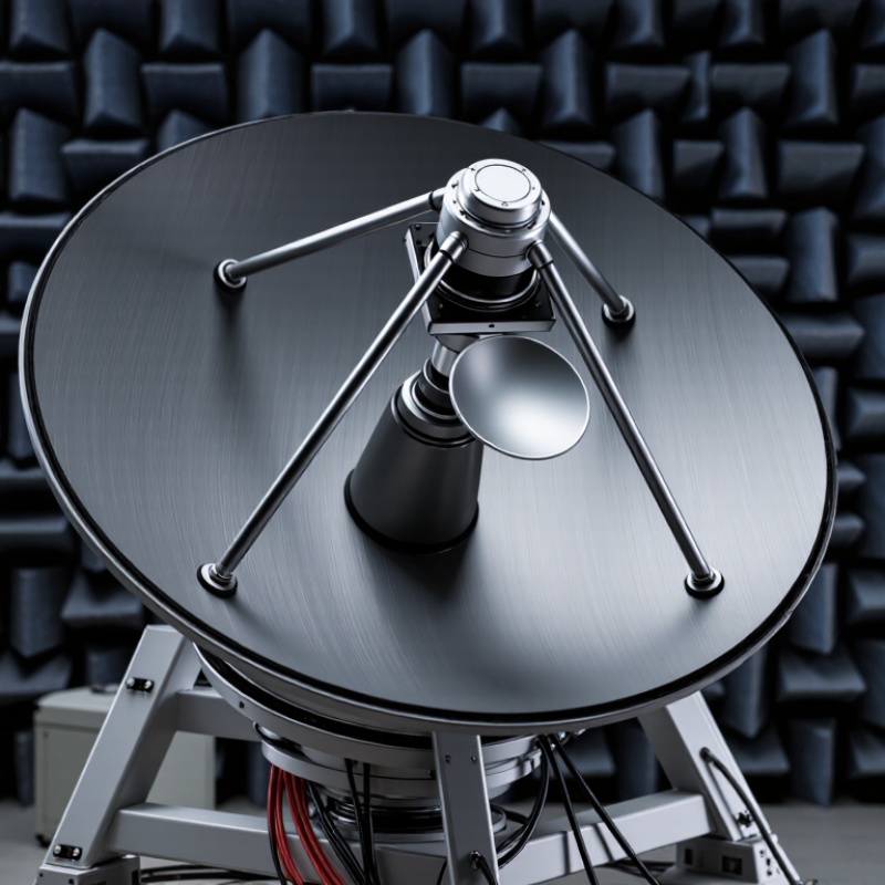
A precision Cassegrain antenna is a dual-reflector system designed to transmit and receive focused radio waves. Its core structure includes a large parabolic main reflector and a smaller convex subreflector. The feed sits near the center of the main reflector, rather than at the dish’s edge. This arrangement creates a compact and mechanically balanced antenna.
The main reflector has a deep, carefully shaped surface. The subreflector hangs in front of it on a rigid support assembly. During transmission, the feed sends energy toward the subreflector. The subreflector redirects that energy toward the main reflector. The main reflector then forms a narrow, nearly parallel beam. Incoming signals follow the reverse path and return to the feed. A waveguide or coaxial transition carries signals between the feed and connected equipment.
Precision depends on more than surface size. Engineers control reflector curvature, spacing, surface smoothness, and feed alignment. Even a small tilt can shift the beam or reduce signal strength. Thermal expansion can also change the focal relationship during long outdoor operation. Field checks may include alignment surveys, radiation-pattern measurements, and inspection of support brackets. No reflector is perfectly exact. Manufacturing tolerance, wind loading, and installation errors still matter. A design can look accurate yet perform poorly if its subreflector is slightly off-center. This is why reliable evaluation combines calculations with measured antenna data.

A precision Cassegrain antenna uses two reflectors to control radio signals with high accuracy. The large primary reflector collects incoming energy and focuses it toward a smaller secondary reflector. That secondary reflector redirects the energy to a feed located behind the main dish. This folded path keeps the structure compact while preserving a long electrical focal length.
The primary reflector shapes the beam and limits unwanted radiation. Its surface must remain smooth because small distortions can reduce gain. The secondary reflector fine-tunes the wavefront before it reaches the feed. Its position and curvature strongly affect focus, phase uniformity, and sidelobe levels. The feed converts guided energy into free-space waves, or reverses that process during reception. Polarization control also matters. A slight mismatch can weaken the received signal.
Support struts hold the secondary reflector in place, but they can interrupt the beam and create scattering. Engineers therefore study their thickness, spacing, and position. Precision mounts allow careful adjustment during installation and tracking. Measurement equipment checks pointing error, return loss, and radiation patterns in practical conditions. Weather adds another variable. Wind, temperature changes, and moisture can shift alignment or alter surface performance. No design is perfect. Even a well-built antenna may need recalibration after transport or long-term exposure. One detail is easy to underestimate: mechanical accuracy directly influences electrical performance.
| Component or Parameter | Typical Specification or Description | Primary Role in Signal Control | Effect on Antenna Performance |
|---|---|---|---|
| Main Reflector | Parabolic dish with a rotationally symmetric reflecting surface | Collects incoming electromagnetic energy and converts it into a focused wavefront | Determines aperture efficiency, gain, beamwidth, and much of the antenna's frequency response |
| Subreflector | Smaller convex reflector positioned near the main reflector's focal region | Redirects the signal between the main reflector and the feed located near the rear of the dish | Supports a compact feed arrangement and helps reduce feed-line loss |
| Feed Horn or Feed Assembly | Waveguide-based feed designed for the operating frequency band | Launches transmitted energy toward the reflectors and receives focused energy in the receive path | Influences impedance matching, polarization purity, sidelobes, and illumination efficiency |
| Feed Support Structure | Rigid struts, tripod, or rear-mounted support system | Maintains the feed and subreflector at their designed positions | Mechanical displacement can cause phase errors, gain reduction, and increased sidelobe levels |
| Reflector Surface Accuracy | Surface deviation typically specified as a fraction of the operating wavelength | Preserves the intended phase relationship across the aperture | Higher accuracy generally improves gain and reduces pattern distortion, especially at higher frequencies |
| Aperture Diameter | Common precision systems range from approximately 0.6 m to several meters | Sets the physical collecting area of the antenna | A larger aperture generally provides higher gain and a narrower main beam at the same frequency |
| Operating Frequency | Application-dependent microwave or millimeter-wave band | Defines the wavelength used to size and evaluate the reflector, feed, and waveguide | Higher frequencies require tighter dimensional tolerances but can deliver narrower beams with the same aperture |
| Polarization Control | Linear or circular polarization, depending on the feed and application | Controls the orientation and electrical characteristics of the transmitted or received field | Accurate polarization alignment improves link quality and reduces cross-polarization interference |
| Antenna Gain | Often approximately 30–55 dBi, depending on aperture size, frequency, and efficiency | Describes the antenna's directional concentration of radiated or received power | Higher gain improves long-distance link budgets but requires more accurate pointing |
| Beamwidth | Typical half-power beamwidth may range from less than 1° to several degrees | Indicates the angular width of the main radiation lobe | A narrow beam improves spatial selectivity but increases sensitivity to alignment errors |
| Pointing and Mounting System | Azimuth-elevation, polar, or other precision tracking mount | Directs the main beam toward the target and compensates for platform or target movement | Pointing accuracy must be appropriate for the antenna's beamwidth to maintain stable signal strength |
| Typical Applications | Satellite communications, radio astronomy, radar, telemetry, and high-capacity microwave links | Provides highly directional transmission and reception where signal isolation is important | Enables high link margins, frequency reuse, interference rejection, and precise spatial observation |
A precision Cassegrain antenna uses two reflectors to direct radio waves along a folded path. The large primary reflector has a concave, dish-like surface. A smaller convex subreflector hangs in front of it. This arrangement guides incoming waves toward a feed placed near the dish center.
When a radio signal arrives, the primary reflector captures and focuses it toward the subreflector. The subreflector then redirects the energy through a central opening or toward a nearby feed. For transmission, the process works in reverse. The feed sends energy to the subreflector, which reflects it onto the primary dish. The dish forms a narrow, controlled beam aimed at a distant target.
This folded geometry keeps sensitive equipment close to the antenna structure. It can also improve mechanical balance and reduce signal loss in long feed paths. The geometry is unforgiving. During installation, technicians measure reflector spacing, surface accuracy, and pointing angles. A small angular error can weaken the beam or increase unwanted side radiation. Wind, temperature changes, and uneven mounting can shift alignment slightly. Real surfaces are never perfectly shaped. That limitation deserves attention. Precision therefore depends on careful manufacturing, stable supports, and repeated field testing, not only on elegant calculations.
A precision Cassegrain antenna uses two reflectors to focus radio energy. The main dish collects signals, while the smaller subreflector redirects them toward the feed. This folded path keeps the antenna compact and supports high gain. It also exposes weak points. Tiny alignment errors can reduce signal quality.
Surface accuracy matters greatly at higher frequencies. Using the Ruze relationship, a 0.5-millimeter surface error can cause roughly 1.7 decibels of loss near the 10-millimeter wavelength. That is not theoretical decoration. A technician may find the error beside a feed support, where thermal expansion changes alignment during operation. Precision machining, rigid mounts, and measured reflector profiles help control this shift.
Polarization accuracy is equally important. A slightly rotated feed can increase cross-polarization and disturb frequency reuse. Modern tracking systems therefore combine precise encoders, calibration routines, and stable control software. The 2024 State of the Satellite Industry Report valued global space revenue at 570 billion dollars in 2023, increasing pressure on ground equipment to perform reliably. ESA’s 2024 Space Environment Report also recorded more than 35,000 regularly tracked objects, making accurate pointing increasingly practical, not optional. Still, perfect alignment is fiction. Cables flex, bearings wear, and weather changes the result. Careful testing remains essential.
A precision Cassegrain antenna uses a main reflector and a smaller subreflector. The feed sits near the rear of the dish. This arrangement creates a compact structure with high gain and a convenient equipment layout.
Typical applications include satellite ground stations, radio astronomy, tracking systems, radar, and long-distance microwave links. Engineers choose this design when narrow beams and stable pointing are important. A large dish may focus energy across thousands of kilometers. However, even a small surface error can reduce efficiency at higher frequencies. Thermal expansion can also shift the beam during daily temperature changes. In practice, alignment often matters more than impressive theoretical gain. A design can look precise on paper and still disappoint in field testing.
Tips: Check reflector accuracy against the operating wavelength. Keep the subreflector centered within tight mechanical tolerances. Measure polarization performance after installation, not only in the workshop. Consider wind loading, ice, rain, cable routing, and maintenance access. The feed and support struts can cause blockage, so their geometry deserves careful review. Use tracking feedback when the beam is extremely narrow. Document every adjustment; small changes can be difficult to reproduce later.
A precision Cassegrain antenna uses a main reflector and a subreflector to focus radio waves toward a feed located near the center of the main dish. The chart shows the approximate half-power beamwidth for a 1.2 m aperture at representative operating frequencies. Higher frequencies produce narrower beams and require tighter mechanical and surface tolerances.
Values are based on the common approximation HPBW ≈ 70λ/D, where λ is wavelength and D is aperture diameter. The examples represent widely used frequency ranges for navigation, radar, satellite communications, and high-capacity point-to-point links. Actual Cassegrain performance also depends on reflector efficiency, subreflector blockage, feed illumination, alignment, polarization, and surface accuracy.